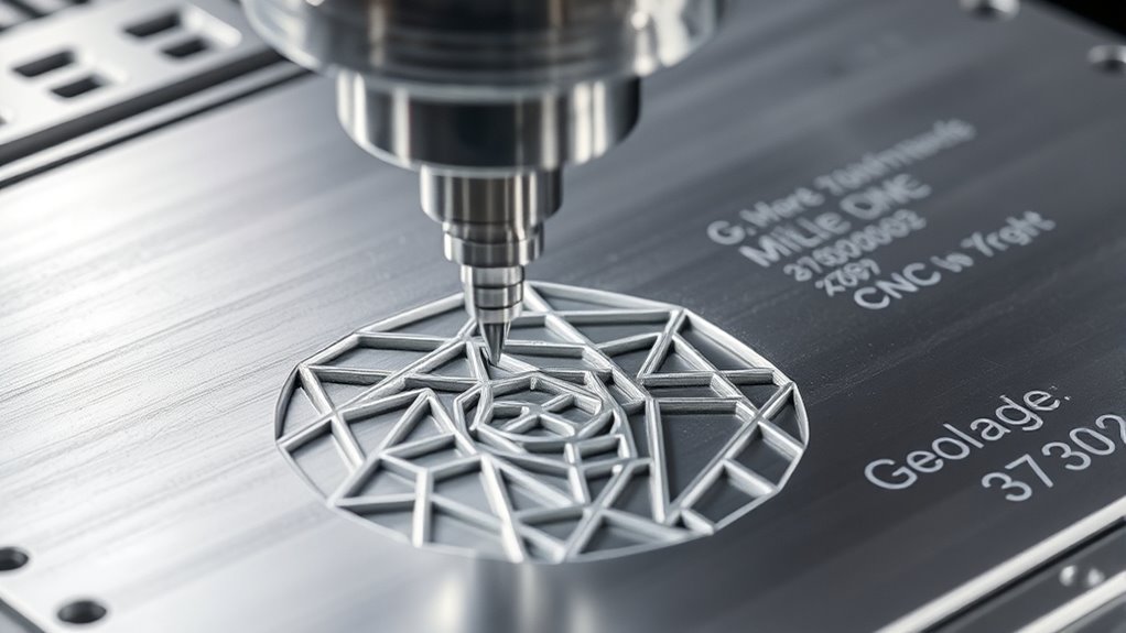
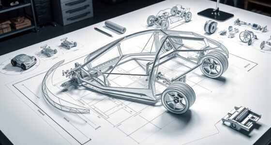
In CNC machining, G-code commands translate your digital models into precise toolpaths by defining linear and circular movements. You’ll use codes like G01 for straight cuts and G02/G03 for arcs, all based on coordinate systems that position your tool accurately. Understanding how these codes reflect geometric features helps you optimize paths, avoid errors, and guarantee your parts match the intended design. Exploring these concepts further reveals how G-codes shape every aspect of your machining process.
Key Takeaways
- G-code commands define precise tool movements and paths in CNC machining, translating digital geometry into physical shapes.
- Linear (G01) and circular (G02, G03) commands specify geometric trajectories for complex part features.
- Coordinate systems and machine calibration ensure G-code accurately reproduces the intended geometry.
- Path optimization and material properties influence the efficiency and accuracy of G-code-generated toolpaths.
- Advanced techniques like multi-axis and macro G-code enhance the machining of complex geometries.
The Fundamentals of G-Code Syntax and Structure
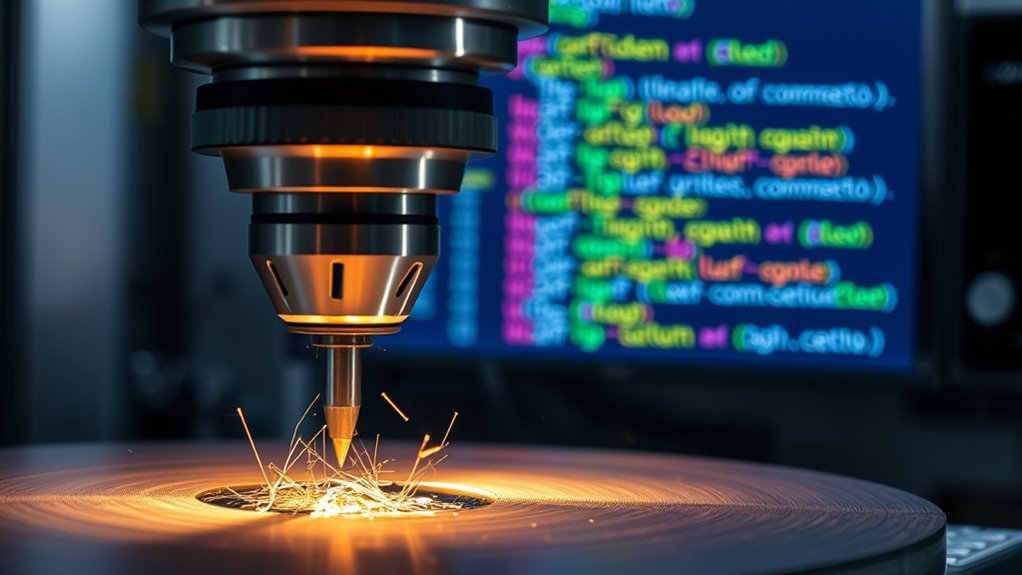
Understanding the fundamentals of G-code syntax and structure is essential for effectively programming CNC machines. First, you need to grasp how G-code communicates commands to control movements and operations. This includes understanding how to specify coordinates, speeds, and tool changes. When preparing for a project, consider material selection, as it influences the G-code you generate and the machine setup process. Properly setting up your machine guarantees that your code runs smoothly and accurately. G-code commands follow a specific structure, with each line representing a command that the machine interprets sequentially. Familiarity with this syntax helps you troubleshoot issues and optimize your machining process, making your work more efficient and precise. Additionally, understanding machine setup procedures ensures that your initial configurations support accurate and consistent results.
How G-Codes Represent Geometric Movements
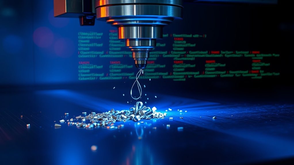
G-codes translate commands into precise geometric movements of the CNC machine. They do this through parametric programming, which allows you to define movements based on variables, enabling flexible and complex tool paths. G-codes specify movements along axes, such as linear (G01) or circular (G02, G03) motions, translating design data into real-world actions. For multi-axis coordination, G-codes manage simultaneous movements across multiple axes, creating smooth, complex shapes. You can control rapid positioning (G00) or precise cutting moves with specific feed rates. By understanding how G-codes encode geometric instructions, you can program intricate paths efficiently, ensuring your machine moves accurately in space, whether for simple parts or sophisticated, multi-axis components. Additionally, mastering the geometric principles underlying G-code commands enhances your ability to troubleshoot and optimize CNC machining operations.
Coordinate Systems and Their Role in CNC Programming
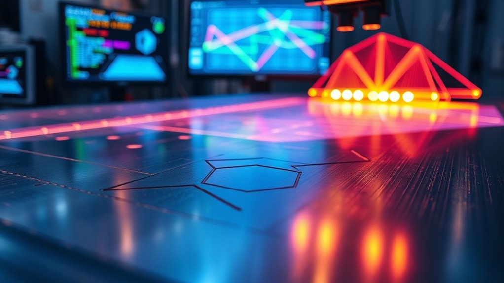
Have you ever wondered how CNC machines interpret your programmed commands to produce precise parts? It all starts with coordinate systems, which define how your commands translate into machine movements. The machine uses coordinate transformation to convert your G-code instructions into actual tool paths, based on the chosen origin selection. You can set the origin at different points—like the machine’s home position, the part’s edge, or a specific feature—affecting how movements are calculated. This setup ensures that all movements are consistent and accurate relative to your reference point. Understanding coordinate systems helps you control tool placement and dimensions precisely, minimizing errors. By mastering origin selection and coordinate transformation, you optimize your CNC programming for efficient, accurate machining and the role of contrast ratio in achieving high-quality images.
Interpreting Line and Arc Commands for Precise Cuts

When working with CNC machines, understanding how line commands control straight cuts guarantees accuracy. Arc commands, on the other hand, help you create smooth curves and complex shapes. Mastering both allows you to produce precise and professional results. Additionally, collaborative environments such as hackathons often utilize digital platforms to simulate and improve CNC programming skills, fostering innovation in manufacturing techniques.
Line Commands and Precision
Understanding how to interpret line and arc commands is essential for achieving precise cuts in CNC machining. When you input G-code, accurate movements depend on your ability to read these commands correctly. For example, straight line commands determine the path your tool follows, impacting the finish quality and dimensional accuracy. Just like fiber optics rely on precise alignments, your CNC machine depends on exact coordinates to prevent errors caused by factors like thermal expansion, which can subtly alter dimensions during machining. Recognizing how line commands translate into physical motion helps you optimize settings for material behavior and machine tolerances. Mastering this interpretation guarantees consistent, high-precision cuts, whether working on intricate designs or larger components. Clear understanding minimizes errors and improves overall machining efficiency. Additionally, understanding G-code commands ensures compatibility with various CNC machines and software, streamlining your workflow and reducing setup time.
Arc Commands and Curves
Mastering arc commands is essential for creating smooth, accurate curves in CNC machining. These commands allow you to produce precise arcs, from simple circles to complex spiral curves, by defining center points and radii. When the design requires more intricate curves, spline interpolation helps generate smooth, flowing paths that go beyond basic arcs. Using G-code arc commands like G02 and G03, you control the direction and shape of curves, ensuring seamless progressions. Proper interpretation of these commands guarantees your machine cuts along the intended geometry, maintaining quality and accuracy. Understanding machine geometry and how it influences tool paths is crucial for achieving precise, professional results in your CNC projects. Whether working with straightforward arcs or sophisticated spiral curves, understanding how to interpret and implement arc commands is key to achieving precise, professional results in your CNC projects.
The Relationship Between Digital Models and G-Code Paths
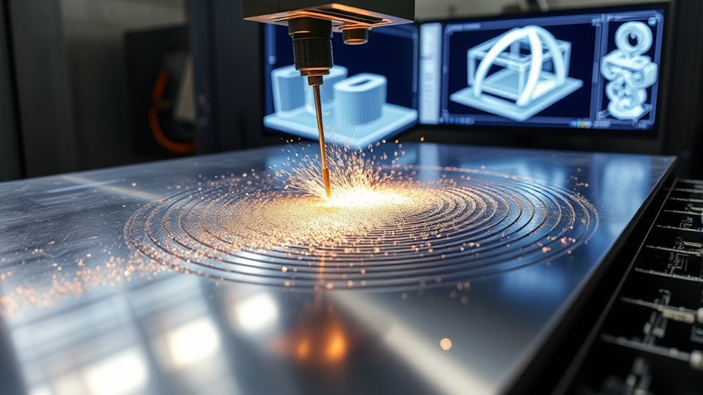
When converting digital models into G-code, you shape the toolpath that guides your machine. Ensuring geometric accuracy during this process can be challenging, especially with complex geometries. To get the best results, you need effective path optimization strategies that balance precision and efficiency. Additionally, considering the role of workspace ergonomics can facilitate smoother operations and reduce errors during machining.
Model to Toolpath Conversion
Converting a digital model into a toolpath involves translating the complex geometry of your design into a series of precise machine movements guided by G-code. This process starts with selecting the right material, as different materials require specific cutting strategies and speeds. Once the model is prepared, CAM software generates the toolpath, ensuring it aligns with your material’s properties and your machining goals. Accurate conversion depends on understanding the relationship between the digital geometry and machine capabilities. Proper machine maintenance ensures smooth operation and consistent results, preventing errors during toolpath execution. By paying attention to material selection and maintaining your CNC machine, you can achieve precise, efficient machining that faithfully reproduces your digital design.
Geometric Accuracy Challenges
Accurate translation of a digital model into G-code paths is essential for ensuring the final machined part matches the intended design. Material properties can cause discrepancies if not properly accounted for, as variations in hardness or thermal expansion affect how the material responds to cutting forces. Additionally, machine calibration plays a critical role; misaligned axes or inaccurate tool offsets can distort the geometry. Even small calibration errors compound during machining, leading to deviations from the digital model. Ensuring consistency between the digital design and the physical part requires regular calibration and understanding of material behavior. Headphones and other equipment used in the workshop can also influence measurement precision and setup accuracy. Without these measures, the G-code paths may not produce the desired geometric accuracy, resulting in parts that don’t meet specifications or quality standards.
Path Optimization Strategies
Effective path optimization bridges the gap between your digital model and the G-code instructions sent to the machine. To do this, consider how material selection impacts cutting paths—softer materials may allow for more aggressive toolpaths, reducing machining time. Proper machine maintenance guarantees your equipment runs smoothly, preventing unexpected deviations that can compromise path efficiency. Streamlining toolpaths minimizes unnecessary movements, saving time and reducing tool wear. By fine-tuning your G-code, you can avoid excessive overlaps and redundant passes, which waste material and energy. Consistent maintenance keeps your machine responsive, ensuring that the optimized paths are executed accurately. Overall, balancing material properties and routine upkeep enhances path efficiency, leading to better surface quality and reduced production costs.
Toolpath Optimization Through Geometric Analysis
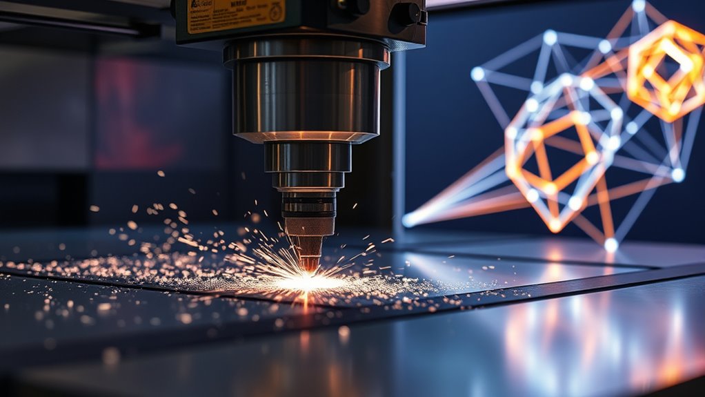
By analyzing the geometry of a part, you can identify the most efficient toolpath to reduce machining time and improve surface quality. Understanding material properties helps you select appropriate cutting parameters, minimizing tool wear and ensuring smooth finishes. Accurate machine calibration is essential; it guarantees that your tool follows the ideal path precisely, avoiding unnecessary movements or errors. Geometric analysis allows you to pinpoint complex features and plan toolpaths that navigate intricate contours efficiently. This reduces idle movements and overlaps, saving time and material. Incorporating material behavior into your planning can further enhance cutting efficiency and tool longevity. By combining a thorough understanding of material behavior with precise calibration, you can optimize your toolpath for both speed and quality. This strategic approach leads to more consistent results and enhances overall productivity in CNC machining.
Common G-Code Commands and Their Geometric Implications

Have you ever wondered how G-code commands translate into precise movements of your CNC machine? Understanding common G-code commands is essential for controlling machine motion and ensuring accurate cuts. Commands like G00 and G01 direct rapid positioning and linear interpolation, shaping the tool’s path. G02 and G03 control clockwise and counterclockwise arcs, influencing curved geometries. Your material selection affects how these commands perform, as different materials respond uniquely to cutting parameters. Proper machine calibration ensures these commands produce expected results, minimizing errors. By mastering these commands and their geometric implications, you can optimize toolpaths, improve surface finish, and reduce machining time. Clear knowledge of G-code fundamentals helps you translate digital instructions into precise physical geometries effectively. Additionally, understanding technology – Whatever Want can help you select the appropriate tools and settings for your specific machining tasks, further enhancing accuracy and efficiency.
Troubleshooting Geometric Errors in G-Code Programming

G-code commands are powerful tools for guiding your CNC machine, but even small errors can lead to significant geometric inaccuracies. To troubleshoot, start with these steps:
- Verify material selection; improper material can cause unexpected tool behavior.
- Check machine calibration; misaligned axes or inaccurate zero points distort geometry.
- Review G-code commands for errors or inconsistencies, ensuring correct coordinates and tool paths.
- Confirm that your machine’s firmware and control software are up to date to prevent communication issues.
- Conduct regular maintenance checks to ensure all mechanical components are properly aligned and functioning correctly.
Advanced Techniques for Complex Geometric Machining

To achieve precise results in complex geometric machining, advanced techniques such as multi-axis machining, parametric programming, and macro G-code are essential. These methods allow you to create intricate parts with high accuracy, leveraging artificial intelligence to optimize tool paths and reduce errors. Material science plays a critical role, enabling you to select the best materials and adapt machining strategies accordingly. By integrating AI-driven algorithms, you can predict material behavior and adjust parameters in real time, enhancing efficiency and precision. Macro G-code simplifies repetitive tasks and complex operations, saving time and minimizing human error. Mastering these advanced techniques allows you to push the boundaries of CNC capabilities, producing complex geometries that meet demanding specifications and innovative design requirements. Understanding butter’s artistic influence can inspire innovative design concepts in CNC machining, especially when creating detailed, artistic, or symbolic features.
Frequently Asked Questions
How Do G-Code Commands Adapt for 3D Surface Machining?
When you adapt G-code commands for 3D surface machining, you focus on precise surface contouring and smooth tool paths. You program commands to control the tool’s movement along complex curves, ensuring consistent contact with the surface. This involves using advanced G-code functions that handle multi-axis motions, allowing you to follow intricate contours accurately and maintain the desired surface finish throughout the machining process.
What Are the Limitations of G-Code in Complex Geometries?
You might find that G-code has limitations with complex geometries due to precision constraints and software limitations. These codes often struggle to accurately represent intricate shapes, leading to potential inaccuracies. As a result, you may need to rely on advanced CAM software or alternative programming methods to better handle complex surfaces. Recognizing these constraints helps you plan machining processes more effectively and avoid unexpected errors in your projects.
How Is Tool Orientation Controlled Through G-Code?
Imagine the precision needed to carve complex shapes—you’re controlling tool orientation with G-code. You set the tool angle to tilt or rotate along specific axes, guiding its exact position. Axis rotation commands dynamically adjust the tool’s orientation during machining, ensuring perfect angles for intricate cuts. This mastery over tool angle and axis rotation keeps your work precise, unleashing the potential to craft complex geometries flawlessly.
Can G-Code Be Automatically Generated From CAD Models?
You can have G-code automatically generated from CAD models using specialized software. CAD integration allows you to import your designs directly, and post-processing software converts these models into G-code tailored for your machine. This process streamlines your workflow, reduces manual coding errors, and speeds up production. With the right tools, you guarantee precise tool paths and efficient machining, making automation a practical option for your manufacturing needs.
How Do Geometric Tolerances Influence G-Code Programming?
Imagine a tightrope walker balancing perfectly—geometric tolerances are your safety net. They influence G-code programming by defining the precision control you need for each feature. Tolerance specifications set the acceptable limits, guiding your tool paths to ensure parts meet quality standards. Ignoring these details risks errors, but with careful planning, you maintain accuracy and consistency, turning complex designs into flawless reality.
Conclusion
Mastering G-code and understanding its geometric principles empower you to craft precise, efficient CNC parts. By analyzing toolpaths and optimizing movements, you guarantee high-quality results. Remember, “A stitch in time saves nine”—investing time in proper programming prevents costly errors later. Keep honing your skills, stay attentive to details, and you’ll open the full potential of CNC machining, turning complex designs into reality with confidence.
