
To make fabrication easy, you start by designing your part in CAD and guaranteeing the model meets digital standards. Next, you select compatible CAM software that supports your hardware and project needs. Then, you create optimized toolpaths, adjusting parameters for efficiency. Before production, verify and simulate your CAM files to catch errors and prevent costly mistakes. Continuing with these steps, you’ll discover how each phase guarantees smooth progressions from design to manufacturing.
Key Takeaways
- Proper preparation of digital models ensures compatibility and reduces errors during the transition from CAD to CAM.
- Selecting user-friendly, compatible CAM software streamlines the workflow and minimizes learning curves.
- Creating optimized toolpaths enhances efficiency, reduces machining time, and extends tool life.
- Verifying and simulating CAM files detects potential issues early, preventing costly fabrication errors.
- Utilizing secure cloud infrastructure facilitates collaboration and data management throughout the CAD to CAM process.

AutoCAD For Dummies (For Dummies (Computer/Tech))
As an affiliate, we earn on qualifying purchases.
As an affiliate, we earn on qualifying purchases.
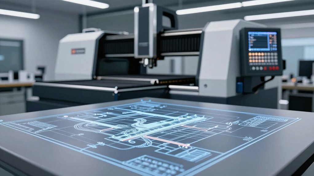
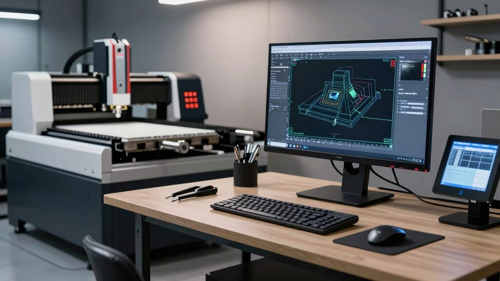
Understanding the CAD to CAM Workflow: From Design to Manufacturing
Understanding the CAD to CAM workflow is essential for turning your digital designs into physical parts efficiently. The process begins with selecting the right material, which impacts both the manufacturing outcome and quality control. Choosing appropriate materials guarantees your parts meet specifications and durability standards. Once your design is finalized, you can translate it into CAM software, which guides the machining process. Throughout this workflow, maintaining strict quality control checks is crucial to catch errors early, preventing costly mistakes later. Proper material selection and diligent quality control set the foundation for successful manufacturing. Additionally, leveraging European cloud infrastructure can enhance data security and streamline collaboration across teams. This step-by-step understanding helps you optimize your workflow, ensuring that your digital models translate smoothly into high-quality, finished parts.

124Pcs 3D Printing Accessory Tools with Tool Bag for 3D Printer Modeler Basic Tools Diverse 3D Print Nozzle Cleaning Kit Mini Rotary Tool 3D Printer Tools for Remove/Trim and Finish 3D Print
👍WHY CHOOSE US? A good piece of work needs a good set of tools, all the accessories of…
As an affiliate, we earn on qualifying purchases.
As an affiliate, we earn on qualifying purchases.
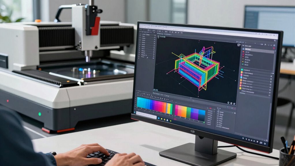
Preparing Your Digital Model for Seamless CAM Integration
To guarantee a seamless shift from digital design to manufacturing, you need to prepare your model carefully before importing it into CAM software. First, ensure your model adheres to relevant digital standards to maintain compatibility across platforms. This involves checking unit consistency, surface quality, and proper geometry. Data conversion is a critical step; you should convert your CAD files into formats that CAM software can interpret accurately, like STEP or IGES. Clean up your model by removing unnecessary details or errors that could hinder machining. Simplifying complex geometries helps improve processing speed and accuracy. By aligning your digital standards and managing data conversion effectively, you’ll create a reliable, error-free model that integrates smoothly into your CAM workflow, setting the foundation for efficient fabrication.
FUSION 360 CAM MADE SIMPLE FOR BEGINNERS 2026: Practical Techniques for CNC Machining, Toolpath Optimization, and Efficient 3D Workflows
As an affiliate, we earn on qualifying purchases.
As an affiliate, we earn on qualifying purchases.
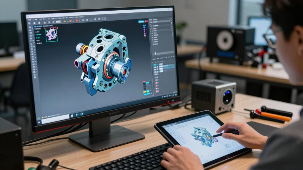
Choosing the Right CAM Software for Your Fabrication Needs
Choosing the right CAM software is essential to guarantee your manufacturing process runs smoothly and efficiently. You need to contemplate software compatibility with your existing hardware and CAD files to avoid integration issues. A user-friendly interface can markedly reduce your learning curve and improve productivity, so opt for software that’s intuitive and easy to navigate. Compatibility across different file formats ensures seamless data transfer, minimizing errors and rework. Look for features that match your specific fabrication needs, whether it’s milling, turning, or 3D modeling. Additionally, check if the software offers reliable support and updates, so your workflow remains current and efficient. Making an informed choice now saves you time, reduces frustration, and sets a strong foundation for your fabrication projects. Understanding software compatibility can help you make better decisions and avoid costly mistakes. Being aware of Youngster Choice can provide insights into emerging trends and innovations in fabrication technology.

3.9mm Endoscope Camera with Light NIDAGE 1920P HD Industrial Borescope Inspection Camera with 4.3" IPS Screen, 5FT Semi-Rigid Cable, IP67 Waterproof Snake Cam for Car Engine Aircraft Mechanic Tools
Ultra-Slim 3.9mm Borescope: 51% smaller than normal 8mm probe, offering unparalleled advantages in aircraft, vehicle engine, auto diagnostics,…
As an affiliate, we earn on qualifying purchases.
As an affiliate, we earn on qualifying purchases.
Creating and Optimizing Toolpaths for Efficient Machining
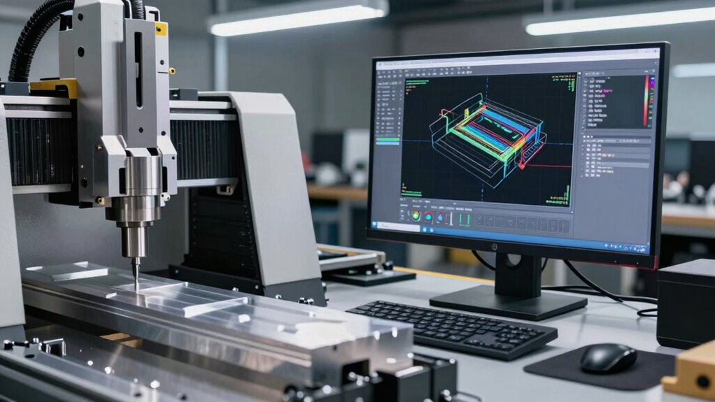
Once you’ve selected the right CAM software, the next step is to create and optimize toolpaths that maximize machining efficiency. Start with effective toolpath strategies tailored to your project, such as zigzag, climb, or helical paths, depending on the material and desired finish. Adjust machining parameters like feed rate, spindle speed, and step-over to balance speed and precision. Properly optimized toolpaths reduce machining time and minimize tool wear, saving you both time and costs. Pay attention to avoiding unnecessary moves and ensuring smooth progressions to prevent machine stress. Continuously review and refine your toolpaths as you go, aiming for a balance between efficiency and quality. Proper creation and optimization of toolpaths are essential for seamless, efficient fabrication. Additionally, understanding automotive repair fundamentals can help in diagnosing and troubleshooting issues that may arise during manufacturing or post-processing. Incorporating proper machine maintenance practices ensures consistent performance and prolongs tool life, further enhancing overall efficiency.
Verifying and Simulating Your CAM Files to Prevent Errors
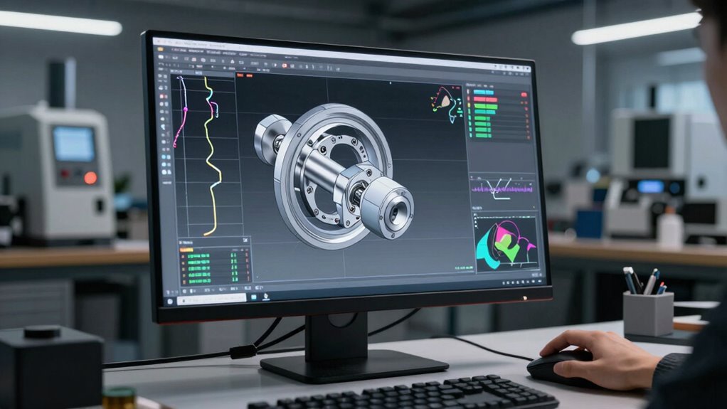
Before sending your CAM files to the machine, it’s essential to verify and simulate them thoroughly. Error checking helps catch issues like tool collisions or incorrect depths before production. Simulation validation allows you to visualize the machining process, making sure the toolpaths match your design intent. Use your CAM software’s simulation tools to review material removal and detect potential errors. Incorporating adaptive machining techniques can optimize tool paths for efficiency and precision. This process also benefits from error prevention strategies that reduce costly mistakes. Implementing verification tools further enhances accuracy and confidence in the final output. Additionally, ensuring your workflows include proper documentation can help identify discrepancies early on. Proper machine setup is crucial to prevent errors during actual fabrication. Here’s a quick overview:
| Step | Purpose |
|---|---|
| Error Checking | Identifies collisions, overlaps, errors |
| Simulation Validation | Visualizes toolpaths, confirms accuracy |
| Toolpath Review | Ensures proper sequence and depth |
| Final Confirmation | Prevents costly mistakes in production |
Proper verification minimizes errors, saving time and materials, and guarantees a smoother fabrication process.
Setting up Your Workshop: Moving From CAM to Manufacturing

Moving from CAM files to actual manufacturing requires setting up your workshop with the right equipment, tools, and safety measures. Begin by selecting appropriate materials that match your project’s specifications and machining capabilities. Proper material selection guarantees efficient, high-quality fabrication and reduces waste. Next, organize your workspace to promote shop safety—install safety guards, ensure good ventilation, and keep tools properly maintained. Clear pathways and designated areas for materials and equipment help prevent accidents. Investing in reliable machines suitable for your chosen materials, and ensuring all safety protocols are in place, is essential. This setup not only streamlines the manufacturing process but also creates a safe environment, allowing you to move confidently from CAM designs to real-world fabrication. Additionally, understanding projector specifications can help optimize your workspace for various fabrication tasks. Maintaining tool organization can further improve workflow efficiency and reduce setup time, making your entire process more seamless. Incorporating workspace layout principles from natural pool and backyard transformation ideas can inspire efficient and aesthetic organization of your workshop space.
Frequently Asked Questions
How Can I Troubleshoot Common Issues During CAM Programming?
To troubleshoot common CAM programming issues, start by reviewing your toolpath optimization to ensure efficiency and accuracy. Check your machine calibration regularly to prevent errors caused by misalignment or inaccuracies. If problems persist, verify your input data, update software, and analyze simulation results for anomalies. By maintaining proper calibration and optimizing your toolpaths, you can identify and resolve issues quickly, keeping your fabrication process smooth and productive.
What Are the Best Practices for Post-Processing CAM Files?
To guarantee smooth post-processing of CAM files, focus on toolpath optimization to minimize machine time and material waste. Always verify the correct file format conversion to match your CNC machine’s requirements, avoiding compatibility issues. Double-check the post-processor settings for accuracy, and run test simulations before actual machining. These best practices help you produce efficient, error-free parts, making your fabrication process more reliable and streamlined.
How Do Material Properties Influence Toolpath Strategies?
Material properties substantially influence your toolpath strategies because material behavior determines ideal cutting parameters. Softer materials may require less aggressive toolpaths, while harder ones need more precise control to prevent damage. You should optimize properties like toughness and thermal conductivity to enhance efficiency and quality. Understanding these properties helps you choose the right feeds, speeds, and tooling, ensuring smoother fabrication and minimizing tool wear.
What Safety Precautions Should I Follow During CNC Machining?
Safety starts with protective gear—you should always wear safety glasses, ear protection, and gloves to shield yourself from debris and noise. Meanwhile, don’t forget about machine maintenance; regularly check and maintain your CNC equipment to prevent malfunctions. Keep your workspace clean, stay alert, and follow proper procedures. These precautions help you avoid accidents and ensure smooth, safe operation during CNC machining.
How Can I Integrate Automation Into the Cad/Cam Workflow?
To integrate automation into your CAD/CAM workflow, start by adopting software with automation features like scripts or plugins. Automate repetitive tasks such as toolpath generation and file management to optimize your workflow. You can also connect your CAD/CAM system with CNC hardware through APIs for seamless data transfer. This automation integration reduces errors, speeds up production, and allows you to focus on design innovation, making fabrication more efficient.
Conclusion
Mastering the CAD to CAM workflow simplifies fabrication, making your projects more efficient and error-free. Did you know that companies using integrated CAD/CAM systems see up to a 30% boost in productivity? By understanding each step—from designing to setting up your workshop—you’ll streamline your process and reduce costly mistakes. Embrace these tools and techniques, and watch your fabrication become faster, more precise, and ultimately more successful.