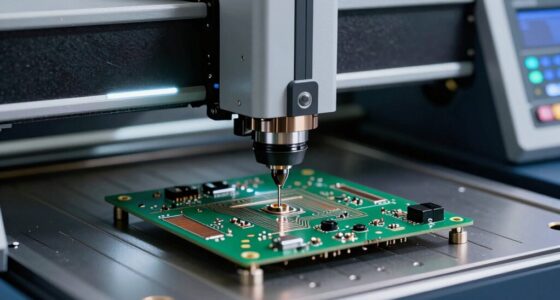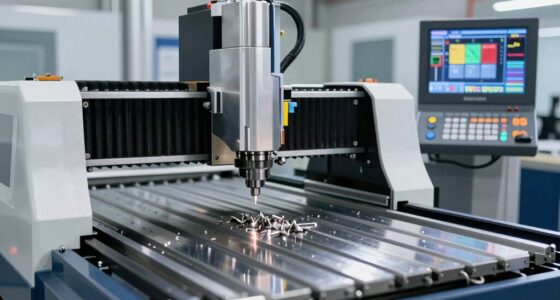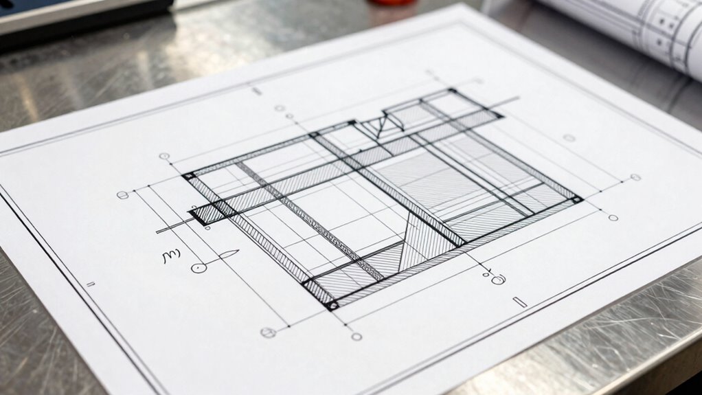

Manufacturing drawings communicate the detailed information needed to turn your design into a precise product. They serve as a common language, specifying materials, dimensions, and tolerances for every component. These drawings help you understand exact requirements and prevent costly mistakes. By using standardized symbols and clear documentation, they guarantee everyone involved interprets the details correctly. Keep exploring, and you’ll discover how these drawings help you achieve better quality and efficiency in manufacturing.
Prime for Young Adults — start your free trial
Fast free delivery, streaming and member deals for eligible 18–24 year olds.
As an affiliate, we earn on qualifying purchases.
Key Takeaways
- The precise dimensions, shapes, and features required to produce each component accurately.
- Material types, finishes, and treatments necessary for optimal part performance.
- Allowed tolerances and permissible variations to ensure quality and fit.
- Standardized symbols and industry conventions for consistent interpretation.
- Assembly instructions and relationships between parts for proper construction.
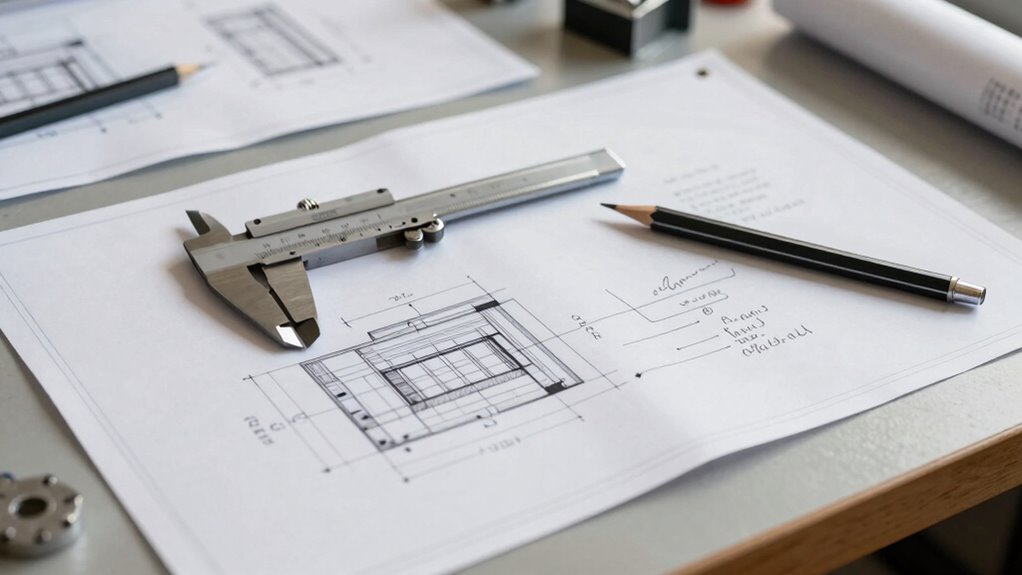
How effectively do you communicate manufacturing drawings to guarantee smooth production? This question is essential because clear communication ensures that every part of the process aligns perfectly with your expectations. Manufacturing drawings serve as the primary language between design and production, translating ideas into tangible components. When you provide detailed drawings, you’re fundamentally giving your team a roadmap to follow, but the clarity of that roadmap determines how smoothly the manufacturing process unfolds. One of the critical elements in these drawings is material specifications. These details specify exactly what materials are to be used, including grades, finishes, and treatments. Clear material specifications prevent costly mistakes, such as using the wrong alloy or incorrect surface treatment, which could compromise the part’s performance. Without precise specifications, there’s a risk of misunderstandings that lead to delays, rework, or even failures in the final product.
Clear material specifications prevent costly mistakes and ensure optimal part performance.
Another indispensable aspect is tolerance clarity. Tolerances define the permissible limits of variation for dimensions and features. When tolerances are clearly communicated, you minimize ambiguity about how precise each part needs to be. This clarity helps manufacturers select the right manufacturing processes and measurement tools, ensuring parts fit and function as intended. Ambiguous or overly tight tolerances can cause production bottlenecks or increased costs, while overly lax tolerances might compromise quality. Striking the right balance and communicating these tolerances clearly on your drawings is fundamental for efficiency and quality control. Additionally, understanding the importance of standardized symbols and annotations in drawings can greatly improve communication, as they ensure everyone involved interprets the information uniformly and accurately. When every detail is meticulously documented, you reduce the chances of misinterpretation, which could otherwise lead to defects or assembly issues. Incorporating industry standards into your drawings further enhances clarity and consistency across different teams and projects. Emphasizing the use of clear documentation helps avoid confusion and ensures that all stakeholders are aligned throughout the process.
Furthermore, effective communication involves using standardized symbols and annotations, ensuring everyone involved—whether on the shop floor or in engineering—is on the same page. Clear, consistent symbols eliminate guesswork and streamline inspections and quality assurance. Ultimately, your goal is to create drawings that are thorough but not overwhelming, allowing your manufacturing team to execute flawlessly. When you pay close attention to material specifications and tolerance clarity, you set a foundation for precision, efficiency, and quality, making sure your manufacturing process is smooth and predictable from start to finish.
As an affiliate, we earn on qualifying purchases.
Frequently Asked Questions
How Do Manufacturing Drawings Vary Across Different Industries?
You’ll notice that manufacturing drawings differ across industries because each follows specific industry standards and emphasizes certain details. For example, aerospace drawings highlight strict material specifications for safety, while automotive drawings focus on assembly tolerances. You should pay attention to these variations because they guide you in meeting industry requirements, ensuring the correct materials are used and that your work aligns with safety, quality, and regulatory standards specific to your industry.
What Are Common Mistakes in Manufacturing Drawings?
You often make mistakes in manufacturing drawings that compromise dimensional accuracy and lead to misunderstandings. Common errors include ambiguous or missing dimensions, unclear material specifications, and inconsistent symbols. These mistakes can cause production delays or defects. To prevent them, double-check all dimensions, clearly specify materials, and adhere to standard drawing conventions. Accurate and detailed drawings ensure your manufacturing process runs smoothly, reducing errors and ensuring quality.
How Do Manufacturing Drawings Impact Product Quality?
Manufacturing drawings directly impact your product quality by ensuring design precision and clear material specifications. When these drawings are accurate and detailed, you reduce errors during production, leading to higher-quality outputs. They guide your team to select the right materials and follow precise processes, minimizing defects and rework. Ultimately, well-crafted drawings help you deliver consistent, reliable products that meet customer expectations and safety standards effectively.
What Software Tools Are Best for Creating Manufacturing Drawings?
You need the right software to craft precise manufacturing drawings. Top choices include AutoCAD and SolidWorks, which excel in 3D modeling and detailed 2D drawings. These tools adhere to CAD standards, ensuring consistency and clarity. Using such software keeps your drawings accurate and professional, but don’t overlook the importance of choosing a program that integrates seamlessly with your workflow—because the right tool can make all the difference in communication and production success.
How Are Manufacturing Drawings Updated During Product Development?
You update manufacturing drawings by tracking design iterations and managing revision control. When changes occur, you revise drawings accordingly, ensuring all updates are documented clearly. You use revision control systems to maintain a history of modifications, preventing confusion and errors. This process helps you keep everyone on the same page, ensuring the drawings accurately reflect the current design status during product development.
material specification templates
As an affiliate, we earn on qualifying purchases.
As an affiliate, we earn on qualifying purchases.
Conclusion
Just like the masterful strokes in a painting, your manufacturing drawings tell a story that guides creation and guarantee precision. They’re the silent heroes behind every successful build, whispering details that keep chaos at bay. When you craft clear, accurate drawings, you’re not just communicating; you’re shaping a legacy of craftsmanship. Remember, in the grand tapestry of production, your drawings are the threads that hold everything together—an enduring ode to meticulous craftsmanship.
tolerance measurement instruments
As an affiliate, we earn on qualifying purchases.
As an affiliate, we earn on qualifying purchases.
standardized engineering symbols
As an affiliate, we earn on qualifying purchases.
As an affiliate, we earn on qualifying purchases.
NFL season / tailgating Picks
team gear
As an affiliate, we earn on qualifying purchases.