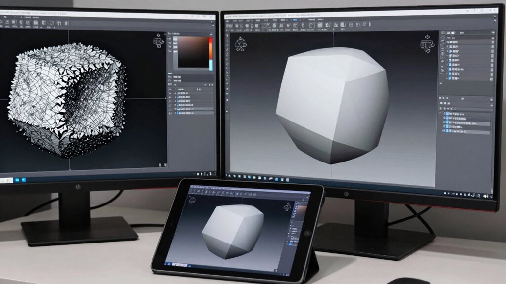
Transforming raw mesh data into clean CAD geometry involves several key steps. First, you verify the mesh for errors or noise, then clean and simplify it to reduce complexity. Next, you repair gaps, holes, and irregularities using specialized tools. Afterward, you convert the optimized mesh into surfaces or solids, focusing on feature extraction and accuracy. Following best practices guarantees a seamless workflow, and continued guidance helps you master each stage with confidence.
Key Takeaways
- Raw mesh data is first inspected for noise, gaps, and non-manifold edges to ensure mesh stability and readiness for processing.
- Mesh cleaning and repair tools are used to fill holes, weld vertices, and smooth irregularities, removing artifacts and errors.
- Mesh simplification and decimation reduce polygon count while preserving critical features, optimizing the model for CAD compatibility.
- The cleaned mesh undergoes feature extraction and surface fitting to generate smooth, accurate surfaces suitable for CAD modeling.
- Final validation verifies the mesh’s quality, ensuring it is free of irregularities and ready for conversion into precise, editable CAD geometry.

ZL180 Handheld GPS for Surveying, High Precision Rugged Land Surveying Equipment for Ranches, Garden, Farmland and Parking Area Distance Measuring
HIGH PRECISION ACCURACY: 2 high sensitivity satellites global GPS + GLONASS coverage for reliable surveying around the world,...
As an affiliate, we earn on qualifying purchases.
Understanding the Challenges of Raw Mesh Data in Reverse Engineering
When working with raw mesh data in reverse engineering, you often encounter significant challenges that can hinder the process. Mesh noise is a common issue, creating irregularities and unwanted artifacts that obscure the true geometry. These imperfections often originate from the initial scan, especially in the point cloud stage, where data points may be sparse or unevenly distributed. The noise complicates efforts to generate accurate CAD models because it distorts surface details and can lead to inaccuracies in the final output. Managing this noise requires careful analysis and sometimes advanced filtering techniques before proceeding. Without addressing these issues early, the mesh can become unreliable, making the subsequent steps of cleaning and modeling much more difficult and time-consuming. Additionally, understanding the concept of Free Floating meshes can be crucial in identifying and correcting issues related to unanchored surface data, which can be a common occurrence in point cloud datasets. Recognizing these mesh imperfections early allows for more effective filtering and cleaning strategies, ultimately improving the accuracy of the reverse engineering process. Implementing proper noise reduction methods and understanding mesh topology are essential to ensure the integrity of the reconstructed geometry. Moreover, applying automated cleaning techniques can significantly speed up the workflow and improve overall results.
Amazon Product B0F6KMH7V8
As an affiliate, we earn on qualifying purchases.
Preparing Your Mesh: Cleaning and Simplifying for Better Results
To get the best results, you need to clean your mesh by removing unnecessary data that can cause errors later. Simplifying complex geometry helps improve accuracy and makes the model easier to work with. Taking these steps guarantees your mesh is optimized for a smoother CAD conversion process.
Removing Unnecessary Mesh Data
Removing unnecessary mesh data is a crucial step in preparing your model for CAD conversion, as excess details can hinder accuracy and increase processing time. You want to eliminate data redundancy, which often results from scan imperfections or high-resolution captures. Use mesh compression techniques to reduce the overall file size without sacrificing essential details. This process helps streamline your mesh, making it easier to work with and ensuring that only relevant geometry remains. Removing redundant or irrelevant data clears the way for more efficient processing and better results downstream. Be careful not to delete critical features; focus on removing areas with unnecessary complexity or noise that won’t contribute to your final model. This step ensures a cleaner, more manageable mesh for subsequent editing and conversion.
Simplifying Geometry for Clarity
After eliminating unnecessary mesh data, focus on simplifying the geometry to improve clarity and accuracy in your model. Simplifying reduces complexity, making it easier to perform texture mapping and guarantee consistent color calibration. Use tools to decimate or retopologize the mesh, removing small or redundant details that don’t add value. This streamlining helps prevent distortions during UV unwrapping and improves the quality of texture application. A cleaner, more manageable mesh results in better visual fidelity and easier editing later. Keep an eye on preserving essential features while removing excess geometry. This step assures your model remains true to the original scan but is optimized for detailed texturing, accurate color calibration, and seamless integration into CAD workflows.

NiesahYan ZL190 Handheld GPS for Surveying, High Precision GPS Surveying Equipment for Mountainous Land Slope and Flat Field Outdoor Use
ACCURATE: Great support 4 high precision satellite system,GPS+BEIDOU+GLONASS+QZSS ,strong satellite signal, small measurement errors, area measurement error in...
As an affiliate, we earn on qualifying purchases.
Using Mesh Repair Tools to Fix Errors and Gaps
You need to identify mesh errors early to prevent problems down the line. Using repair tools, you can target specific issues like gaps or holes quickly and effectively. Always verify the mesh integrity afterward to guarantee your model is solid and ready for CAD conversion. Incorporating mesh repair techniques can further streamline this process and ensure optimal results. Being aware of mesh integrity is crucial for maintaining model quality during the transformation process.
Detect Mesh Errors Early
Have you ever encountered unexpected gaps or distortions in your mesh model? Detecting mesh errors early helps you catch problems like mesh noise or topology issues before they worsen. Use repair tools that highlight irregularities, such as non-manifold edges or holes, so you can address them promptly. These tools often identify areas where the mesh doesn’t follow a clean, consistent topology, preventing future complications during processing. Spotting errors early saves time and avoids complicated fixes later. Regularly inspecting your mesh with diagnostic features ensures you don’t overlook small issues that could cause major setbacks. By proactively identifying and fixing these errors, you set a solid foundation for cleaner, more accurate geometry as you move forward in your CAD workflow. Additionally, understanding the principles behind mesh repair tools can help inform better investment decisions during your project planning.
Apply Targeted Repairs Effectively
Once you’ve identified mesh errors, applying targeted repairs with the right tools can quickly restore model integrity. Use mesh segmentation to isolate problematic areas, making repairs more precise. Focus on specific errors like gaps, holes, or non-manifold edges, and apply targeted repairs directly to those regions. Repair tools such as fill, weld, or merge vertices help close gaps and smooth out irregularities efficiently. By segmenting the mesh first, you prevent unnecessary edits to unaffected areas, saving time and maintaining accuracy. This focused approach ensures that each repair addresses the root cause without introducing new issues. Effective targeted repairs streamline the process, giving you a cleaner, more reliable mesh ready for the next steps in your CAD workflow. Understanding mesh repair techniques can further improve your results and help you maintain the integrity of your models. Additionally, mastering mesh repair strategies is essential for producing high-quality geometry that meets industry standards.
Verify Mesh Integrity
How can you guarantee your mesh is free of errors before moving forward in your CAD workflow? By verifying mesh integrity, you ensure your model’s stability and accuracy. Use mesh repair tools to identify and fix errors like gaps, holes, or non-manifold edges that compromise mesh stability. Check for data redundancy, which can cause unnecessary complexity and slow down processing. Removing redundant data improves overall mesh quality, making it more reliable for further steps. Run automated diagnostics to detect corrupted areas and perform targeted repairs. Confirm that the mesh is watertight and free of errors before proceeding. This step assures your raw scan data transitions smoothly into clean, manageable geometry suitable for CAD modeling.

ZL190PLUS Land Surveying Equipment, Handheld GPS for Surveying with 3.2 Inch Color Screen, Multi-GNSS Support, 7 Measuring Models for Measuring Land Area, Length,Slope and Save Coordinates Points
Large Screen:Large 3.2" sunlight-readable color display with 240 x 320 display pixels for improved readability,even in bright sunlight
As an affiliate, we earn on qualifying purchases.
Decimating and Reducing Mesh Complexity Without Losing Detail
Reducing mesh complexity is essential for efficient CAD models, but it can be challenging to do so without sacrificing important details. Mesh decimation techniques allow you to lower polygon counts while maintaining the overall shape and features. Focus on algorithms that prioritize detail preservation, ensuring critical edges and surfaces stay intact. Tools often offer adjustable settings, so you can find a balance between simplification and accuracy. You should review the decimated mesh carefully, checking that key features remain sharp and recognizable. Proper decimation reduces file size, speeds up processing, and improves compatibility with CAD workflows. By carefully applying mesh decimation, you streamline your model without compromising the essential details needed for precise CAD conversion and downstream design work.
Converting Meshes to CAD: Choosing the Right Method and Software
Converting meshes into precise CAD models requires selecting the right method and software to guarantee accuracy and efficiency. You need tools that support effective mesh optimization, reducing complexity while preserving detail. The software should assure CAD compatibility, allowing seamless import and manipulation of the mesh data. Popular options include dedicated reverse engineering programs and CAD-specific plugins that automate surface fitting and parametric modeling. Consider your project’s needs: if high precision is essential, choose software that offers advanced mesh repair and optimization features. These tools help streamline the conversion process, minimize errors, and produce clean, usable CAD models. By selecting compatible software that emphasizes mesh optimization and CAD compatibility, you set a strong foundation for a successful transition from raw scan data to professional CAD geometry. Understanding mesh repair techniques is also crucial for achieving high-quality results.
Trimming and Extracting Key Features From the Mesh

To effectively prepare your mesh for CAD conversion, you need to identify the key geometry that defines your model’s shape. Removing unnecessary meshes helps streamline the process and improves accuracy. Clearly defining boundaries guarantees your extracted features are precise and ready for seamless integration into your CAD workflow.
Identifying Key Geometry
How do you accurately identify the essential features of a mesh for CAD conversion? The key lies in understanding mesh topology, which reveals how vertices, edges, and faces connect. By analyzing this structure, you can pinpoint critical features like edges, corners, and surface contours. Feature recognition tools help automate this process, highlighting geometric elements that define the object’s shape. Focus on areas where topology indicates sharp changes or significant detail, as these are crucial for creating accurate CAD models. Trimming unnecessary mesh regions further clarifies the geometry, ensuring you extract only the essential features. Recognizing topological features enables more precise feature extraction, which is vital for successful CAD translation. Utilizing topology analysis techniques can significantly enhance the accuracy of feature detection. This step prepares your mesh for precise translation into clean, editable CAD geometry, setting the stage for smooth, reliable modeling downstream.
Removing Unnecessary Meshes
Removing unnecessary meshes is a crucial step in preparing your model for CAD conversion. By focusing on mesh simplification, you eliminate unnecessary data that can clutter your model and hinder accurate processing. Trim away extraneous meshes that don’t contribute to the key features of your object, reducing complexity and improving efficiency. This step helps you isolate essential surfaces and details, making it easier to define clear boundaries later. Simplifying the mesh also decreases file size and computational load, speeding up subsequent steps. Be precise when trimming, ensuring you only remove non-essential parts. Removing unnecessary meshes sharpens your model’s focus, streamlines the workflow, and sets a solid foundation for clean, accurate CAD geometry. Paying attention to care & maintenance ensures your model remains in optimal condition for future modifications and uses.
Defining Clear Boundaries
Defining clear boundaries is essential for accurately translating your mesh into CAD. Good boundary definition ensures that edges are distinct and features are correctly isolated, improving edge clarity. To achieve this, you need to trim unnecessary parts and extract key features precisely. Use tools that allow you to mark or cut along specific edges, creating well-defined boundaries. Clear boundaries help prevent ambiguities during modeling and guarantee smooth transitions. Organize your approach with the following ideas:
| Boundary Definition | Edge Clarity |
|---|---|
| Trim unwanted areas | Highlight key edges |
| Isolate features | Clarify sharp vs. smooth |
| Mark boundary lines | Define distinct edges |
| Remove noise | Enhance edge contrast |
| Confirm boundaries | Improve feature recognition |
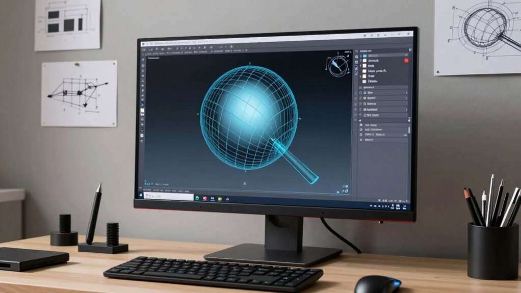
Creating Accurate Surface Models From Mesh Data
Creating accurate surface models from mesh data involves transforming complex, often noisy, 3D scans into smooth, precise representations suitable for CAD applications. Achieving high mesh accuracy is essential to preserve the details of the original object while minimizing errors introduced during scanning. You’ll focus on refining the mesh to improve surface continuity, ensuring the surface flows seamlessly across the model without abrupt changes or gaps. Techniques such as smoothing, hole filling, and targeted remeshing help eliminate noise and irregularities. By carefully adjusting these parameters, you develop a clean, well-defined surface that accurately reflects the scanned object. This process lays the foundation for reliable CAD modeling, enabling precise measurements and further design work without distortion or loss of critical features. Additionally, understanding the importance of mesh quality assessment ensures that the final model meets the necessary standards for accuracy and detail.
Generating Solid Geometry and Parametric CAD Models
Once you have a clean, accurate surface model from mesh data, the next step is to convert that geometry into solid forms suitable for CAD design. You begin with mesh segmentation, dividing the model into meaningful regions based on geometric features. This process helps identify key components and simplifies complex surfaces. Next, you perform feature extraction, pinpointing edges, holes, fillets, and other critical design elements. These features serve as the foundation for constructing solid geometry, ensuring that your model maintains true design intent. Using CAD software, you then create parametric models by defining features parametrically, allowing easy modifications later. This approach transforms raw mesh data into precise, editable CAD models, ready for detailed design, analysis, and manufacturing.
Optimizing and Validating Your CAD Model for Manufacturing or Analysis
To guarantee your CAD model is suitable for manufacturing or analysis, you need to optimize and validate its geometry. Begin by reducing mesh size through mesh compression, which decreases file size and enhances processing speed without sacrificing detail. Address data redundancy by removing overlapping or unnecessary elements that can cause inaccuracies or slow down simulations. Validate the model by checking for gaps, non-manifold edges, or irregularities that could impair manufacturing or analysis. Ensuring the geometry is clean and optimized minimizes errors during downstream processes and improves performance. Additionally, employing mesh validation tools can help identify subtle issues that might otherwise go unnoticed. By streamlining your model, you facilitate easier integration into manufacturing workflows and more reliable analysis results. Proper validation and optimization are essential steps to ensure your CAD model performs as intended in real-world applications.
Tips and Best Practices for a Smooth Scan-to-CAD Workflow
A smooth scan-to-CAD workflow starts with careful preparation and attention to detail at every step. Begin by choosing the right scan resolution—higher resolution captures more detail but increases file size, so balance it based on your accuracy needs. When capturing scans, focus on maintaining good mesh topology; well-organized topology ensures easier cleaning and editing later. Avoid dense, irregular meshes that can complicate processing. Use consistent scan angles and overlapping scans to improve accuracy and reduce gaps. During post-processing, clean and optimize the mesh, preserving topology that supports smooth surface reconstruction. These practices minimize errors and facilitate a seamless progression from raw mesh to clean CAD geometry, saving you time and ensuring high-quality results throughout your workflow.
Frequently Asked Questions
How Do I Choose the Best Software for Mesh-To-Cad Conversion?
You should choose software that offers excellent compatibility with your existing tools and file formats, ensuring smooth integration. Look for an intuitive user interface that makes the mesh-to-CAD conversion process straightforward, reducing your learning curve. Consider features like automatic cleanup, precision, and support options. Test demos if possible, so you can evaluate how well the software fits your workflow and whether it simplifies your mesh to CAD conversion tasks.
What Are Common Mistakes to Avoid During Mesh Cleanup?
Imagine sculpting a masterpiece—don’t let mesh artifacts and missing details tarnish your work. You should avoid rushing cleanup, as it may smooth out essential features or introduce new artifacts. Be cautious with aggressive decimation, which can erase details, and ignore small holes or gaps, leading to structural issues. Always review your mesh carefully, maintaining a balance between cleaning and preserving accuracy to make certain a clean, precise geometry.
Can Raw Mesh Data Be Used Directly for Manufacturing?
Raw mesh data usually can’t be used directly for manufacturing because it often lacks the necessary mesh accuracy and detailed precision. You need to clean and optimize the mesh first, guaranteeing it meets manufacturing compatibility standards. This step helps avoid issues like inaccuracies or errors during production. So, always refine your raw mesh to ensure it’s accurate and compatible with your manufacturing process for the best results.
How Do Different Mesh Formats Affect the Conversion Process?
Imagine your project hinges on the mesh format, and data compatibility is key. Different mesh formats, like OBJ, STL, or PLY, each have unique structures that impact how smoothly you can convert raw meshes into CAD. Some formats preserve detail better, while others streamline processing. Choosing the right mesh format guarantees a smoother conversion, reduces errors, and saves you time by making data compatibility straightforward and efficient.
What Are the Limitations of Automated Mesh Repair Tools?
Automated mesh repair tools often struggle with complex geometry, limiting their ability to maintain mesh accuracy. They may miss small holes or produce oversimplified repairs, affecting detail. While repair speed is usually fast, these tools sometimes require manual adjustments afterward, which can be time-consuming. Relying solely on automation risks compromising the integrity of your model, so it’s crucial to review repairs carefully for best possible results.
Conclusion
Remember, a clean mesh is the foundation of a successful scan-to-CAD process. By carefully preparing, repairing, and converting your data, you turn raw scans into precise, usable models. Think of it like sculpting; you chip away the excess to reveal the form beneath. Stay patient, follow best practices, and you’ll transform complex meshes into perfect CAD geometry—proving that a journey of a thousand miles begins with a single step.